3d Molecular Designs Worksheet Answers
Summary
Students are challenged to use computer-aided design (CAD) software to create "complete" 3D-printed molecule models that take into consideration bond angles and lone-pair positioning. To begin, they explore two interactive digital simulations: "build a molecule" and "molecule shapes." This aids them in comparing and contrasting existing molecular modeling approaches—ball-and-stick, space-filling, and valence shell electron pair repulsion (VSEPR)—so as to understand their benefits and limitations. In order to complete a worksheet that requires them to draw Lewis dot structures, they determine the characteristics and geometries (valence electrons, polar bonds, shape type, bond angles and overall polarity) of 12 molecules. They also use molecular model kits. These explorations and exercises prepare them to design and 3D print their own models to most accurately depict molecules. Pre/Post quizzes, a step-by-step Blender 3D software tutorial handout and a worksheet are provided.This engineering curriculum aligns to Next Generation Science Standards (NGSS).
Engineering Connection
Being able to visualize molecules helps chemistry students (and chemical engineers) analyze the distribution pattern of atoms around a central atom and study its bond types. But the traditional molecular ball-and-stick models typically used for this purpose have limitations—they do not account for lone-pair electrons and the hole positions around the central atom are pre-set to accommodate bonding. As a result, students have difficulty merging the use of the VSEPR theory with molecular models. To overcome these limitations, this activity employs CAD software and 3D printers to enable students to create their own more complete molecule representations. Once students understand the significance of accurately evaluating molecular models and their features—characteristics such as bond angle, lone-pair electrons—and how those features dictate molecular geometry, they can take advantage of 3D technology to better predict chemical and physical properties.
This skillset has significant real-world chemical engineering applications for influencing molecular geometry to create chemical compounds such as polymers, paper, dyes, drugs, plastics, fertilizers, foods and petrochemicals that are custom designed for clients and consumers. The development of these end products requires a solid understanding of molecular structure and can ultimately affect our health, environment and cost of living. With the use of 3D printers, chemical engineers can begin to further enhance product quality by developing prototypes that add functionality to complement specific chemical reactions.
Learning Objectives
After this activity, students should be able to:
- Draw Lewis dot diagrams for various examples of covalent molecules and polyatomic ions.
- Create models of molecules/ions, including their molecular structures and geometries, using CAD software and 3D printers.
- Apply the VSEPR theory to predict molecular geometry and polarity.
Educational Standards Each TeachEngineering lesson or activity is correlated to one or more K-12 science, technology, engineering or math (STEM) educational standards.
All 100,000+ K-12 STEM standards covered in TeachEngineering are collected, maintained and packaged by the Achievement Standards Network (ASN), a project of D2L (www.achievementstandards.org).
In the ASN, standards are hierarchically structured: first by source; e.g., by state; within source by type; e.g., science or mathematics; within type by subtype, then by grade, etc.
Each TeachEngineering lesson or activity is correlated to one or more K-12 science, technology, engineering or math (STEM) educational standards.
All 100,000+ K-12 STEM standards covered in TeachEngineering are collected, maintained and packaged by the Achievement Standards Network (ASN), a project of D2L (www.achievementstandards.org).
In the ASN, standards are hierarchically structured: first by source; e.g., by state; within source by type; e.g., science or mathematics; within type by subtype, then by grade, etc.
NGSS: Next Generation Science Standards - Science
| NGSS Performance Expectation | ||
|---|---|---|
| HS-PS1-1. Use the periodic table as a model to predict the relative properties of elements based on the patterns of electrons in the outermost energy level of atoms. (Grades 9 - 12) Do you agree with this alignment? Thanks for your feedback! | ||
| Click to view other curriculum aligned to this Performance Expectation | ||
| This activity focuses on the following Three Dimensional Learning aspects of NGSS: | ||
| Science & Engineering Practices | Disciplinary Core Ideas | Crosscutting Concepts |
| Use a model to predict the relationships between systems or between components of a system. Alignment agreement: Thanks for your feedback! | Each atom has a charged substructure consisting of a nucleus, which is made of protons and neutrons, surrounded by electrons. Alignment agreement: Thanks for your feedback! The periodic table orders elements horizontally by the number of protons in the atom's nucleus and places those with similar chemical properties in columns. The repeating patterns of this table reflect patterns of outer electron states.Alignment agreement: Thanks for your feedback! | Different patterns may be observed at each of the scales at which a system is studied and can provide evidence for causality in explanations of phenomena. Alignment agreement: Thanks for your feedback! |
Common Core State Standards - Math
- Apply geometric concepts in modeling situations (Grades 9 - 12) More Details
View aligned curriculum
Do you agree with this alignment? Thanks for your feedback!
- Visualize relationships between two-dimensional and three-dimensional objects (Grades 9 - 12) More Details
View aligned curriculum
Do you agree with this alignment? Thanks for your feedback!
International Technology and Engineering Educators Association - Technology
- Students will develop an understanding of the relationships among technologies and the connections between technology and other fields of study. (Grades K - 12) More Details
View aligned curriculum
Do you agree with this alignment? Thanks for your feedback!
- A prototype is a working model used to test a design concept by making actual observations and necessary adjustments. (Grades 9 - 12) More Details
View aligned curriculum
Do you agree with this alignment? Thanks for your feedback!
State Standards
Suggest an alignment not listed aboveMaterials List
Each group needs:
- ball-and-stick molecular model building kit, available from many vendors such Frey Scientific
- paper and pencils, to create a compare/contrast chart
- Pre-Activity Quiz, one per student
- Lewis Dot Structures and Molecule Geometries Worksheet, one per student
- Post-Activity Quiz, one per student
- Blender Tutorial Step-by-Step Procedure, one per group
- computer with Blender software installed, open source 3D creation software, free at https://www.blender.org/; alternatively, use other CAD software you have available
To share with the entire class:
- computer with Internet access and projector, to show students two interactive simulations at https://phet.colorado.edu/ (requires Java) and a six-minute Blender software tutorial (or else students watch the latter on individual team computers)
- a 3D prototype of an atomic model of water, or any other example produced from a 3D printer, to show the class
- 3D printer
- ABS filament for 3D printing
- (optional) Visual Aid, contains graphics that you may want to project to show the class
Worksheets and Attachments
Visit [www.teachengineering.org/activities/view/fiu_models_activity1] to print or download.More Curriculum Like This
Upper Elementary Lesson 
Surfactants: Helping Molecules Get Along
Students learn about the basics of molecules and how they interact with each other. They learn about the idea of polar and non-polar molecules and how they act with other fluids and surfaces. Students acquire a conceptual understanding of surfactant molecules and how they work on a molecular level. ...

Pre-Req Knowledge
A basic knowledge of atomic structure including the three main atomic particles, their locations and relative charges.
Introduction/Motivation
(Be ready to show the class a digital, three-dimensional image of a rotating water molecule. Make sure that you have Java downloaded; then, go to https://phet.colorado.edu/ and type "build a molecule" in the search box. Under Simulations, select "Build a Molecule." Play the file.)
The properties of molecules are dictated by their composition and geometries. If we can identify the molecular structure and bond angles that are unique to specific types of molecular geometries, then we can identify a pattern of chemical behavior with a unique set of chemical and physical properties.
How can we identify the molecular geometry of a molecule? What is the best way to model a molecule? How can we compare and contrast various molecular models? The most traditional way to model molecules is the ball-and-stick method. What are its drawbacks? This method does not indicate the presence of any lone-pair electrons, which influence molecular geometry.
(Gesture to the projected 3D molecule image.) Let's use this software application to construct some molecules. By doing this, we'll be able to identify similarities and differences between the types of molecular models available. (Ask a student to point and drag the atoms at the bottom of the screen to model water, oxygen, hydrogen, carbon dioxide and nitrogen molecules. Direct the student to click the 3D option to view the molecule. The student may select the space-filling model or the ball-and-stick model. Ask the class to compare and contrast the two models.)
(Next, present a VSEPR theory molecule model at the same website, https://phet.colorado.edu/. Type "molecule shape" in the search box. Under Simulations, select "Molecule Shapes." Select the model option box. Ask another student to build the same molecules as before, but use the options to create a VSEPR model. Ask students to make observations about the model. Expect them to notice that this model has the option to use a lone pair on the molecule, but be unsure about whether or not to use it. Then select the real molecule option, as displayed on the screen, to introduce the concept of the VSEPR theory by explaining the lone-pair feature and how it affects the overall arrangement and bond angles of each molecule. Because a lone electron pair encompasses more relative volume around a central atom within a molecule, comparison to a shared electron pair, the presence of a lone electron pair causes a neighboring shared electron pair to shift away, which affects the overall molecule geometry.)
(Depending on the class level, consider using all of the examples available in the interactive simulation as well as projecting Figure 1 [also available in the Visual Aid], which shows examples of ball-and-stick molecule models compared to space-filling models for water and methane. Pros and cons: The space-filling models are helpful in showing how much space the atoms occupy within the molecule, while the ball-and-stick models are helpful in showing the chemical bonds and their orientations around the central atom in their pre-fixed positions.)
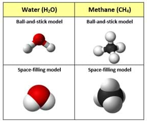
copyright
Copyright © (clockwise from top left) 2008 Ben Mills, 2009 Ben Mills, 2006 Dbc334 and Jynto, 2006 Dbc334 and Jynto; all from Wikimedia Commons https://commons.wikimedia.org/wiki/File:Water-3D-balls-A.png https://commons.wikimedia.org/wiki/File:Methane-CRC-MW-3D-balls.png https://commons.wikimedia.org/wiki/File:Methane-3D-space-filling.svg https://commons.wikimedia.org/wiki/File:Water_molecule_3D.svg
(Direct students to create a chart to compare and contrast the three molecular modeling methods discussed, including the strengths and limitations of—and any other observations about—each model.)
(Present a 3D prototype of an atomic model of water or any other example produced from a 3D printer.) How does this 3D printout compare and contrast with the other models? (See Figure 2; also available in the Visual Aid.) Expect students to be able to discern the difficulty in establishing an accurate bond angle between the atoms for any molecule on the 3D prototype as well as a symbolic means of representing the lone electron pairs and their pronounced influence on bond angles. Also expect them to be able to discern that regardless of the model type, none can fully and realistically represent a real-life molecules on the nano scale.)
Today, your challenge is to work in teams to engineer your own "complete" molecular model using any of the just-discussed examples from the interactive simulation to accommodate various bond angles around the central atom and lone-pair electrons.
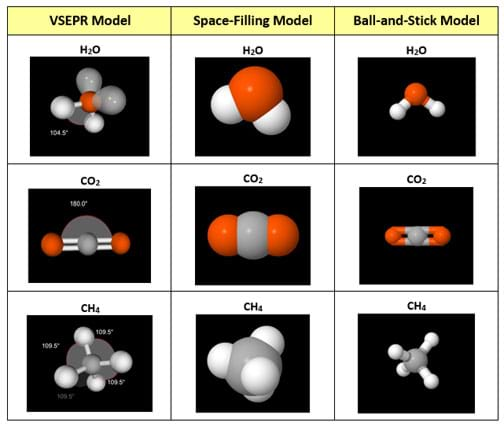
copyright
Copyright © 2016 PhET Interactive Simulations, University of Colorado Boulder CC-BY https://phet.colorado.edu
Procedure
Background
When two non-metallic atoms covalently bond, either a neutral molecule or a polyatomic ion is formed, which involves the sharing of valence electrons between both atoms. As a result, each atom achieves a filled valence shell of electrons similar to the nearest noble gas. A filled outer shell usually means that the atom has acquired a total of eight valence electrons (often called the octet rule). One exception is hydrogen, which requires the acquisition of only two electrons, similar to the helium atom.
As illustrated in Figure 3, a Lewis dot diagram shows only the valence electrons distributed between the covalently bonded atoms. An unshared electron pair or lone pair is represented by two paired dots. A short line (a single bond) is made of two electrons. Two short lines (a double bond) is made of four electrons. Three short lines (a triple bond) is made of six electrons.

copyright
Copyright © 2016 Conrad Faine, Nanotechnology RET Program, College of Engineering and Computing, Florida International University
The valence shell electron pair repulsion theory, otherwise known as the VSEPR theory, explains the cause and effect that occurs when lone pairs and bonded electron pairs move as far apart as possible from each other—thus resulting in the molecule's final geometric configuration (see Table 1 for commonly encountered molecular geometries; also available in the Visual Aid).
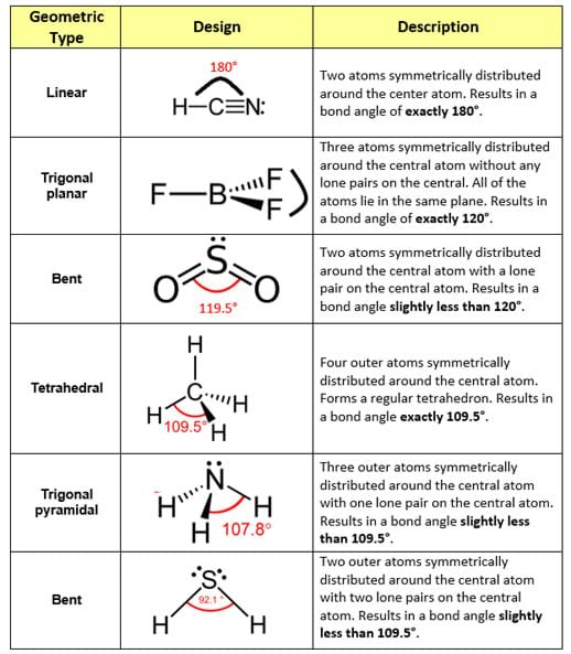
copyright
Copyright © 2009 Ericvse; 2009 Ben Mills; 2007 Richtom80 ; 2010 Jynto; 2009 Ben Mills; 2007 Benjah-bmm27; all from Wikimedia Commons https://commons.wikimedia.org/wiki/File:Hydrogen-cyanide-2D.svg https://commons.wikimedia.org/wiki/File:Boron-trifluoride-2D-dimensions.png https://commons.wikimedia.org/wiki/File:Sulfur-dioxide-2D.svg https://en.wikipedia.org/wiki/File:Methane-2D-dimensions.svg https://en.wikipedia.org/wiki/File:Ammonia-dimensions-from-Greenwood%26Earnshaw-2D.png https://commons.wikimedia.org/wiki/File:Hydrogen-sulfide-2D-dimensions.svg
In a sense, the resultant geometric molecular configuration can be compared to a tug-of-war. This pulling effect is known as electronegativity. If the net pull favors one direction over another, the overall molecular polarity is polar.
Electronegativity "strength" varies from one atom to the next. On the periodic table, electronegativity increases from left to right across a period and decreases going down a group. When the electronegativity difference is 0.5 to 0.9 between both atoms in a molecule, an unequal sharing of valence electrons occurs. In this particular case, the atom with the greater electronegativity forms a partial negative charge, δ-. The atom with the lower electronegativity forms a partial positive charge, δ+ (see Figure 4).
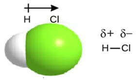
copyright
Copyright © 2012 Adam Rędzikowski, Wikimedia Commons (further modified) https://commons.wikimedia.org/wiki/File:Hydrogen_chloride_3d_bonds.png
The result is a dipole molecule with a polar covalent bond. However, when the electronegativity difference is 0 between both atoms, an unequal sharing of valence electrons occurs. The result is a nonpolar covalent bond. See Figure 5.

copyright
Copyright © 2007 Alessio Damato; 2016 Ohnodoctor; 2006 Benjah-bmm27; 2009 Ben Mills; all from Wikimedia Commons https://commons.wikimedia.org/wiki/File:Carbon-dioxide-2D-dimensions.svg https://commons.wikimedia.org/wiki/File:Dichloromethane_molecular_structure.png https://commons.wikimedia.org/wiki/File:Water-2D-labelled.png https://commons.wikimedia.org/wiki/File:Ammonia-dimensions-from-Greenwood%26Earnshaw-2D.png
A polar molecule is said to have a net dipole moment if its polar bonds are distributed asymmetrically around the central atom. Molecules with lone pairs on the central atom surrounded by different perimeter atoms usually result in polar molecules.
By contrast, if the central atom is surrounded by nonpolar bonds, the molecule is considered nonpolar. By the same token, if the central atom is surrounded by polar bonds distributed in a symmetrical arrangement, the molecule is considered nonpolar as well since the individual bond polarities cancel out.
Before the Activity
- Make copies of the Pre-Activity Quiz, Lewis Dot Structures and Molecule Geometries Worksheet, and Post-Activity Quiz, one each per student, and the Blender Tutorial Step-by-Step Procedure, one per group.
- Prepare example 3D-printed molecular models such as for water and carbon dioxide.
- Before presenting the Introduction/Motivation content to the class, prepare to show two online simulations using a computer and projector, both at https://phet.colorado.edu/. Make sure that you have Java downloaded first. Details provided in the Introduction/Motivation section.
- If desired and as necessary, arrange to show students the Visual Aid images during the activity.
With the Students
- Administer the pre-activity quiz.
- Introduction and Background Information: (30 minutes) Present to the class the Introductory/Motivation content, including two online interactive simulations and the engineering challenge.
- Divide the class into groups of four students each.
- Part 1—Lewis Structures: Hand out the worksheets. Explain that students are to sketch out a Lewis dot structure for each of the 12 molecules listed on the worksheet: CH4, CO2, NH3, H2O, N2, SO2, O2, O3, CO, CO3, NO3, and CF2Cl2 (CFC, chlorofluorocarbon). Instructions are provided on the worksheet. Remind students to use one dash to represent a bonded pair of electrons and two dots to represent lone-pair electrons.
- Part 2—Molecular Polarity: Have groups each use a molecular model kit to try to construct a three-dimensional model of each of the 12 molecules and polyatomic ions listed on the worksheet. Direct students to sketch out a detailed picture of each model. Explain that:
- Each colored ball matches a different atom or different group of atoms in the kit. Refer to the color key provided in the kit.
- Each short stick represents a single bond.
- Use the flexible springs to construct multiple bonds. Use two springs for a double bond and three springs for a triple bond.
- Using a VSEPR reference table—such as Table 1 or the one in Wikipedia at https://en.wikipedia.org/wiki/VSEPR_theory—have students match and record the appropriate shape for each molecule along with its corresponding bond angles. Remind students to only record the bond angles if the molecule has no definite central atom.
- Have students determine the polarity of the bonds for each molecule and its overall symmetry, identifying whether the molecule is polar or nonpolar.
- Part 3—Software-Engineered 3D Model: As a class or in groups, have students watch the six-minute Blender software YouTube tutorial that uses a methane molecule as an example: https://www.youtube.com/watch?v=MTXQM_Fy5ug. This provides step-by-step instructions that will be important for them to know.
- Provide students with copies of the Blender tutorial handout. Direct groups to use the Blender software to each design and then construct a 3D model example (see Figure 6). Remind students to make sure to incorporate the correct bond angles and show where the unshared pairs of electrons are located, if any.
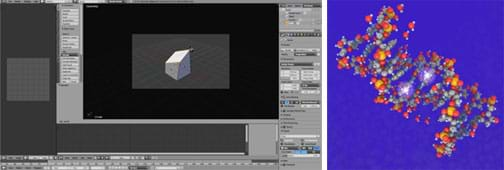
copyright
Copyright © (left) 2016 Wolfgang Gelbricht, Wikimedia Commons; (right) 2015 Qubeat, Wikimedia Commons https://commons.wikimedia.org/wiki/File:Blender-_Polygon_rotieren.png https://commons.wikimedia.org/wiki/File:DNA_methylation_H_o.jpg
- When finished, have each group print its 3D molecule directly from the Blender software.
- Have each group present its design and answer the questions provided in the Assessment section.
- Direct students to draw on their worksheets a 3D diagram for each molecule.
- For comparison purposes, assign each group one molecule to 3D print (or let them pick one).
- Have each group compare its 3D printout with a 3D ball-and-stick version of its molecule. Expect students to be able to compare and contrast the advantages and disadvantages of each version to support the VSEPR theory. Possible answers are listed below.
Ball-and-stick advantages:
- All of the atoms and bonds are arranged in 3D.
- Each ball is pre-set with holes that permit single double or triple bonds.
- The bond angles of the pre-set holes create reasonable representations of real molecules.
- The length of each stick is relatively proportional to real bond lengths.
Ball-and-stick disadvantages:
- The model does not display a representation of any unshared electron pairs around any of the atoms.
- Double or triple bonds do not accurately depict real sigma or pi bonds.
- All of the model atoms are the same size, thus each atom does not proportionately depict actual atom sizes.
3D printout advantages:
- Bond angles must be determined or estimated from scratch to agree with the VSEPR theory.
- The VSEPR theory must be applied to estimate the angle created by the unshared electron pair(s).
- Actual atomic size is considered to relatively create the size of the representative atoms.
- Actual bond length is considered to relatively create the length of the representative bond(s).
3D printout disadvantages:
- Requires more time for completion.
- Requires cost-availability of materials to create the 3D printout.
- Potentially a limited time-frame for creation if using trial period software.
- Conclude by administering the post-activity quiz.
Vocabulary/Definitions
bond polarity: When valence electrons are shared between atoms.
electronegativity: The ability of an atom to attract electrons when the atom is in a compound.
molecular polarity: The sum of all the individual bond polarities.
nonpolar covalent bond: A bond type that occurs when the atoms in the bond pull equally.
polar covalent bond: A bond type that occurs between atoms when the valence electrons are shared unequally.
VSEPR theory: A theory that explains how the repulsion between electron pairs causes the molecular shapes to adjust so that the valence-electron pairs stay as far apart as possible.
Assessment
Pre-Activity Assessment
Pre-Quiz: Before starting the activity, administer the six-question, short-answer Pre-Activity Quiz to gauge student base understanding about molecular bonds, electronegativity, molecular polarity, familiarity with ball-and-stick molecular model kits, VSEPR theory, and molecule geometries.
Activity Embedded Assessment
Worksheets: As prompted in the activity, have students complete the Lewis Dot Structures and Molecule Geometries Worksheet, which guides them to draw Lewis dot structures for 12 chemicals, as well research and report other relevant information. Review their answers to gauge their comprehension.
Design Presentations: After constructing the 3D molecular models, have each group present its designs and answer the following questions:
- How does your 3D design compare with the traditional ball-and-stick model? (Example answer: More realistic, for example, bond angle positions were measured to determine where the adjacent bonds would be located around the central atom.)
- How did you decide on the final construction of your model? (Example answer: The lone-pair electrons on the central atom had the largest influence on the final relative positions of the adjacent bonds. The other surrounding atoms were distributed evenly because of electron-electron repulsion among themselves.)
- How were you able to accommodate for the lone-pair electrons in your design? (Example answer: We created a tangible symbolic representation for the lone-pair electrons on the central atom.)
- How did the lone-pair electrons affect the bond angles of your designs? (Example answer: It caused the other adjacent bonds around the central atom to shift so as to be further away from the lone-pairs.)
- How does 3D printing provide a more accurate representation of your molecular designs? (Example answer: It accounts for the lone-pair electrons, bond angles, and the number of bonds between the central atom and each surrounding atom.)
- How could you further improve your designs? (Example answer: Since every atom has a specific atomic radius, we could create an atomic radius scale system to determine the relative atomic sizes, and then create those atoms to reflect the relative sizes.)
Post-Activity Assessment
Post-Quiz: At activity end, administer the seven-question Post-Activity Quiz, which asks students to fill in a table, providing the chemical formula, a VSEPR shape sketch and whether or not it is a "greenhouse gas" for seven chemicals: carbon dioxide, methane, nitrogen, oxygen, ozone, sulfur dioxide and water. Review their answers to gauge their depth of understanding.
Additional Multimedia Support
As part of the Introduction/Motivation content presented to students, show them the interactive simulations—"build a molecule" and "molecule shapes"—at https://phet.colorado.edu/.
As part of the Procedure, show students the six-minute "Blender Tutorial - Chemistry, Making 3D Models of Molecules, Making a Methane Molecule," at https://www.youtube.com/watch?v=MTXQM_Fy5ug.
Copyright
© 2017 by Regents of the University of Colorado; original © 2016 Florida International UniversityContributors
Conrad Faine; Kerlyn PradaSupporting Program
Nanotechnology Research Experience for Teachers Program, College of Engineering and Computing, Florida International UniversityAcknowledgements
This activity was created in FIU's College of Engineering and Computing in collaboration with its Colleges of Arts and Sciences and Education. This material is based in part upon work supported by the National Science Foundation under grant no. EEC 1300711—RET in Engineering and Computer Science: Nanotechnology Research Experiences for Teachers at FIU. Any opinions, findings, and conclusions or recommendations expressed in this material are those of the authors and do not necessarily reflect the views of the National Science Foundation.
Special thanks to the following people at FIU: Masoud Milani, associate professor, School of Computing and Information Sciences; Benjamin Boesl, mechanical and materials; Patrick Roman, MEMS – AMERI Lab Manager; Nezih Pala, electrical and computer engineering; Stephanie Strange, associate director of the Office of Student Access and Success; and Juan Manjarres, 3D "Make It Lab."
Last modified: November 23, 2021
3d Molecular Designs Worksheet Answers
Source: https://www.teachengineering.org/activities/view/fiu_models_activity1
Posted by: dentonconly1969.blogspot.com

0 Response to "3d Molecular Designs Worksheet Answers"
Post a Comment